More Power!
Can you imagine life without your smartphone? How could we possibly function? Our entire life is now centralized in a single mobile location. In a split second we can update our activities to 100’s of people, trade stock, binge watch our favorite show, summon a ride, order a pizza, and the list goes on and on. As our hunger for these services grows at an exponential rate, technologies that provide these services must evolve in order to meet this demand while simultaneously improving the overall cost structure to consumers and service operators.

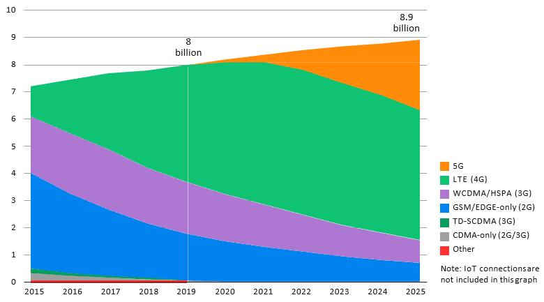
Figure 1: Mobile subscriptions by technology (billions)
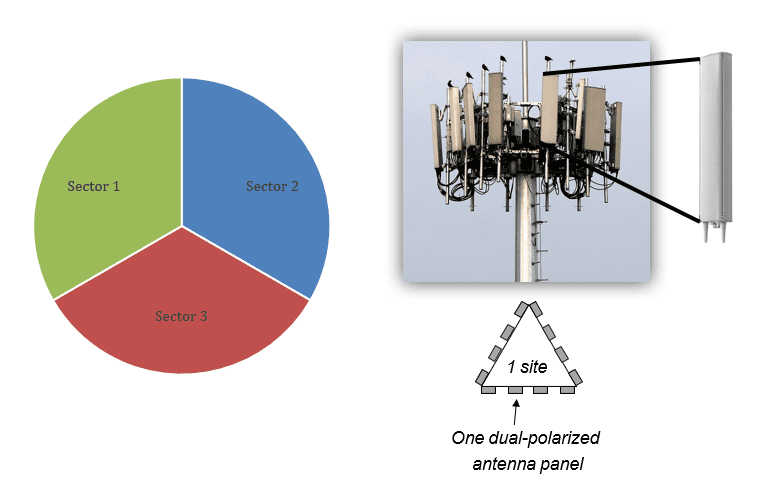
The technologies that have made this all possible are listed in Figure 1, along with their expected growth rates. As Figure 1 implies, with time, overall mobile subscription is steadily increasing, while legacy systems are gradually being phased out as consumers demand more data (throughput). All cellular systems are comprised of a grouping of antennas that are arranged into segments, or sectors, that focus radio frequency (RF) energy in the direction of the user (Figure 2). This sectorization architecture allows for frequency reuse and transmitter power management as the system adjusts to the number of users and their distance from each cell tower sector. While as effective as this approach has been at providing our wireless broadband needs, it is an extremely inefficient use of RF power since only a fraction of that energy will reach the individual user within that sector. This factor is relevant to the overall cost to the service operator (lower margins) which translates to higher cost to the consumer.

Figure 2: Typical cell tower sectorized configuration
How do we meet the market demand for more data while keeping the cost down and encouraging system operators to invest in new technology? We need a solution that reduces the number of cell sites, cooling of those sites, improves transmit power efficiency, and finally, throughput (more data). As seen in Figure 3, over 50% of CAPEX is allocated to air conditioning, while 41% of OPEX is allocated to electricity, and only 7% towards the actual transmission of data. Cell systems are comprised of four main segments, antenna array, power amplifier, radio head and baseband unit (BBU). Most of the cooling resources are devoted to the (BBU).

Figure 3: Radio access network energy consumption
In 1-2G systems, primarily talk only systems, the radio head and BBU were housed together which proved to be inefficient as it relates to thermal management (Figure 4). With the advent of 3-4G systems, the radio head was combined with the power amplifier section and moved close to the antenna while replacing the coax connection (1-2G) with a fiber fronthaul (3-4G), thus reducing RF power losses which improves overall system efficiency. Reducing site related cooling requirements by distributing the system sections has assisted in the overall operating cost of the cell site. Next generation systems, such as 5G, go a step further and virtualize the BBU in fiber fed data farms where centralized cooling can be implemented thus reducing even further both CAPEX and OPEX.

Figure 4: 1-4G cellular infrastructure evolution
Why MIMO?
With traditional sectorized cell systems as previously mentioned, most of the RF energy intended for the user is wasted and spread over a large area—therefore increasing the power requirement of the amplifiers that deliver the energy to the antenna in order to meet the system link budget (Figure 5). Wouldn’t it be great if instead of throwing that energy away we could focus it directly towards the user? Fortunately, we do. MIMO (multiple input multiple output) schemes allow the use of several antenna spaced at specific distance, typically half a wavelength of the signal carrier frequency, where the transmit baseband signal is split into multiple I/Q baseband channels and transmitted to up to eight MIMO antennas. For this to work, the cell tower (base station) transmits a pilot signal through all antennas which are received by the user’s device.

Figure 5: Path loss vs single an eight element MIMO beam forming technique
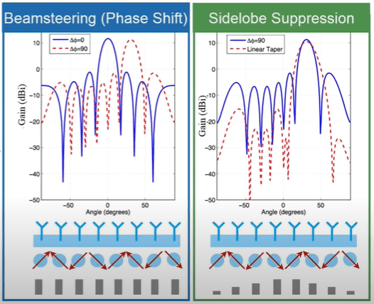
The phase and magnitude difference of these pilot signals are determined in the digital domain. Once known, the device transmits the phase and magnitude difference of each pilot back to the base station where the phase and magnitude of the I/Q data streams are adjusted to compensate for these differences. This beam steering technique (Figure 6) has the effect of transmitting M number signals in phase relative to the position of the device constructively summing together, thereby improving signal to noise. This implementation is referred to as single-User MIMO (SU MIMO) which was introduced in 4G LTE networks. The limitations with SU MIMO is that the computational workload is placed on the device, which is typically battery powered, requires dual antennas on the device side as well and the max limit of eight (M) elements in the array.

Figure 6: M8 MIMO beam steering and sidelobe example
Massive MIMO?
If MIMO is great, it makes sense to make it massive—and that’s precisely what it is. Massive MIMO is a key element in the 5G cellular networks. Figure 7 is broken down into two-tiers, hotspot tier and coverage tier. The hotspot tier operates at mm-wave and will be used for high-density short-range cells and the coverage tier operates sub 6 GHz (primary band is 3.4-3.8 GHz) for use in elevated base stations with outdoor to indoor penetration. Massive MIMO can extend the antenna count on the base station to greater than 200 which dramatically increases effective antenna gain, beam focus, reduces sidelobe interference and individual power amplifier output requirement. Base station beam pointing, and channel estimation is achieved by uplink pilot signal from the user which elevates the computation overhead of the user device thus reducing battery consumption. As 5G continues to rollout Massive MIMO will continue to play a major role in the future expansion of wireless broadband technology.

Figure 7: Massive MIMO base station graphic
References
– Demystifying 5G and the Evolution to Massive MIMO for Increased Capacity and Profit – Prof. Corbett Rowell Rohode & Schwartz
– Ericsson Mobility Report Nov 2019
– Massive MIMO for 5G below 6 GHz – Associate Prof Emil Bjornson
About NuWaves
NuWaves RF Solutions is a premier supplier of RF and Microwave solutions for Department of Defense (DoD), government, and industrial customers. An RF engineering powerhouse, NuWaves offers a broad range of design and engineering services related to the development and sustainment of key communications, telemetry and electronic warfare systems, as well as a complete line of commercially available RF products. NuWaves’ products include wideband frequency converters, high-efficiency and miniature solid-state power amplifiers and bidirectional amplifiers, high intercept low noise amplifiers and miniature RF filters. NuWaves RF Solutions…Trusted RF Solutions™.


Comments are closed